Barrier Gate Installation A Step – by – Step Guide for a Hassle – Free Setup

Installing a ACCESS TECH DC brushless barrier gate requires precision and adherence to safety protocols. This step-by-step guide will walk you through the process to ensure a smooth and secure setup.

Safety First

Before starting, remember these critical safety warnings:

  1. Automatic barriers are designed only for vehicles; pedestrians must use separate entrances.
  2. Installation and maintenance must be performed by qualified personnel.
  3. Always cut off power during installation or maintenance.
  4. Never operate the barrier without the boom installed, as this can cause severe injury.
  5. Keep the switch at least 1.5m above the ground to prevent access by children.

Pre – Installation Preparation

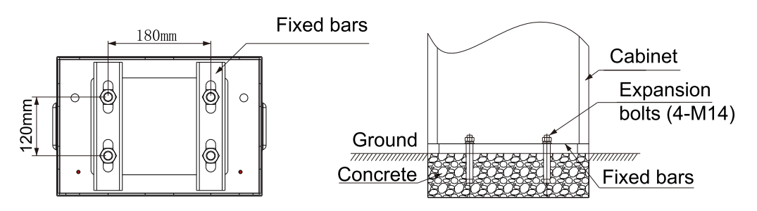
Gather all necessary tools and components, including the barrier cabinet, boom, fixed bars, expansion bolts (4 – M14), electric drill (21mm bit), screwdrivers, and a #14 spanner. Ensure the installation site has a stable concrete foundation to support the barrier’s weight.

Step 1: Cabinet Installation

  1. Open the cabinet door and remove the attachment pack.
  2. Position the cabinet at the desired location.
  3. Place the fixed bars inside the bottom of the cabinet.
  4. Mark the boreholes for the expansion bolts using the fixed bars as a guide.
  5. Move the cabinet aside and drill 110 – 120mm deep holes with a 21mm electric drill.
  6. Insert the expansion bolts into the holes.
  7. Return the cabinet to its position, place the fixed bars back, and tighten the expansion bolts securely.
fix barrier gate

Step 2: Boom Installation

1.Loosen the screws and move the springs away from the spring support .

disassemble the spring

2.Use the manual release handle to steer the boom holder to a horizontal position.

adjust the boom holder

3.Install the boom and outer boom holder according to Fig.

install the boom

4.Fix the boom support on the ground. Adjust its height so that the rubber pad touches the boom when it is in the horizontal position.

fix the boom holder

Step 3: Spring Balance Adjustment

The springs are pre – balanced at the factory, but adjustments are needed if the boom length or weight changes (e.g., adding a stop sign).

1.Determine the required spring quantity and size based on the boom length (X):

4≤X<5: 1 spring of Φ4 or Φ5

5≤X<5.5: 2 springs

5.5≤X<6: 2 springs of Φ5

2.Adjust the spring nuts:

Tighten clockwise if the boom weight increases.

Loosen counter – clockwise if the weight decreases.

Ensure all nuts are turned the same number of cycles to avoid uneven loads.

adjust the spring

3.Fine – tune by loosening the adjusting insert, moving the boom to 30° – 60°, and adjusting based on boom movement direction (Fig. 10). Tighten the linkage nuts after adjustment.

Step 4: Direction Configuration (If Needed)

To change the barrier direction from right to left:

  1. Loosen the spring nut with a #14 spanner.
  2. Remove the screws and take off the balance rod.
  3. Rotate the balance rod 180° and reattach it to the shaft.
  4. Move the two screws to the opposite side.
  5. Connect the rod to the balance arm, ensuring the boom support is vertical and the rod forms a straight line with three points.
  6. Move the spring to the other side and secure it.

Step 5: Electrical Connections

Refer to the controller’s electrical diagram for proper wiring. Key points:

  1. Connect the ground wire and current breaker.
  2. Terminal Battery 12V + and 12V – are for backup power during outages.
  3. Terminal Power 24V + and 24V – are for motor operation (disconnect the main power first).

Step 6: Testing and Final Checks

  1. Power on the barrier and test the remote control operation.
  2. Verify the boom moves smoothly to open (vertical) and close (horizontal) positions.
  3. Check the spring balance again to ensure the boom stays in place without sagging or drifting.
  4. Confirm all safety features, such as limit protections, are functioning correctly.

By following these steps, you can ensure a hassle – free installation of your barrier gate, providing reliable and safe vehicle access control for years to come.

Leave a Reply

Your email address will not be published. Required fields are marked *