Our Location
UNIT 1406A, 14/F, THE BELGIAN BANK BUILDING, NOS. 721-725 NATHAN ROAD, MONG KOK HONG KONG

UNIT 1406A, 14/F, THE BELGIAN BANK BUILDING, NOS. 721-725 NATHAN ROAD, MONG KOK HONG KONG

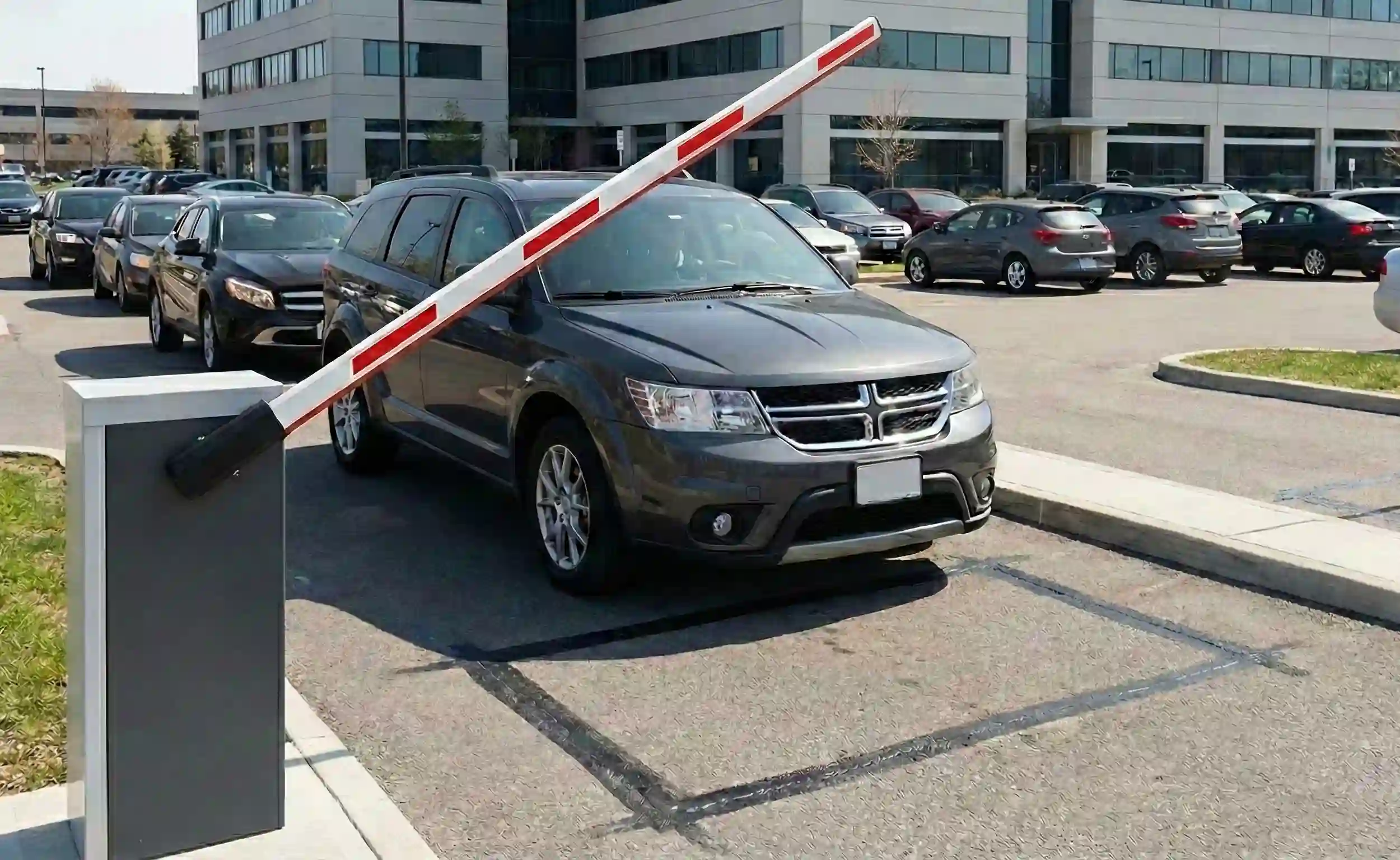
In modern access control systems, the automated Barrier Gate is the visible executive arm. However, the component that truly endows the system with “intelligence” and “safety” is often hidden beneath the asphalt, invisible to the naked eye: the Vehicle Loop Detector and its associated inductive ground loop.
An unstable loop detector system can lead to frustrating failures where the gate won’t close automatically, or worse, catastrophic “boom-on-car” accidents.
This article provides a deep technical analysis of how inductive loop detectors work, the critical engineering requirements for wiring geometry, strategies for handling complex environments like reinforced concrete, and the essential logic behind vehicle anti-crushing safety.
A common misconception is that ground loops detect vehicles based on weight. They do not. A loop detector system is essentially part of a large LC oscillator circuit that detects disturbances in a magnetic field caused by conductive metal objects.
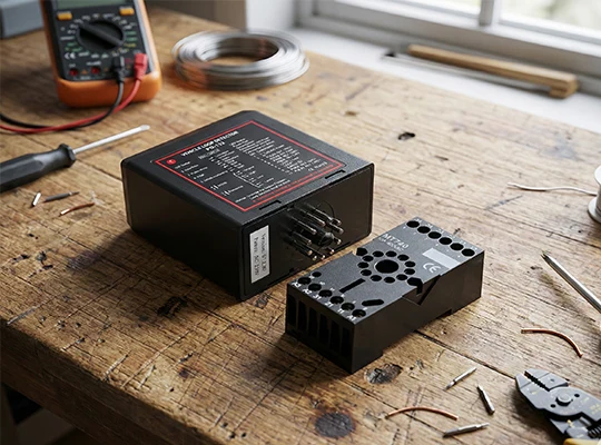
A loop detection system consists of two main parts: multi-turn wires buried in the ground (the Loop, acting as Inductor L) and the detector unit sitting in the gate controller cabinet (containing the Capacitor C and excitation circuitry).
When powered, the detector unit sends an AC current of a specific frequency through the buried loop. According to the principles of electromagnetism, this energized loop creates a stable, alternating magnetic field around itself, primarily directly above the road surface. At this stage, the entire LC circuit oscillates at a stable baseline frequency.
When a vehicle (a large conductive metal mass) enters this alternating magnetic field, the physics changes:
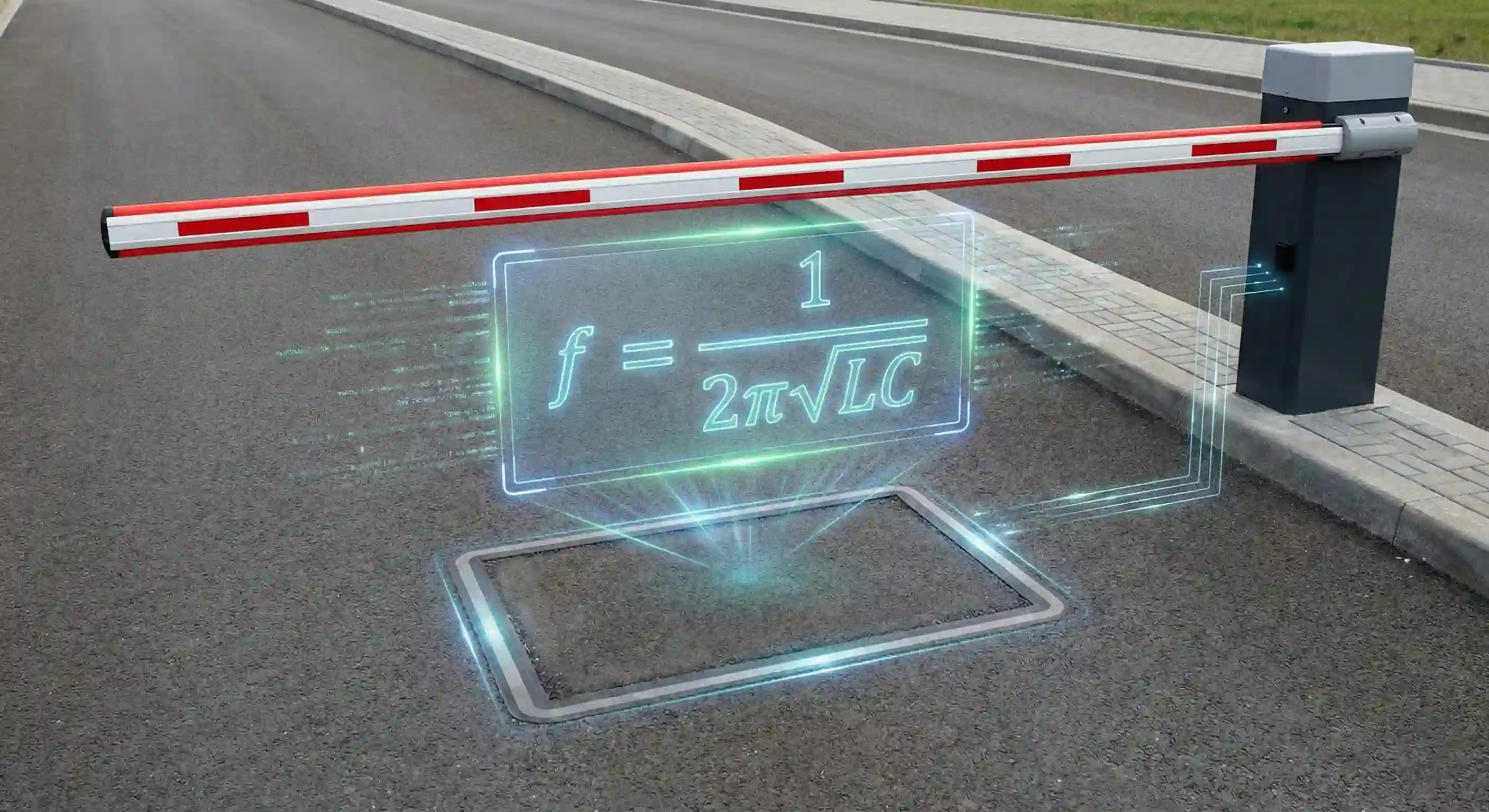
The oscillation frequency of an LC circuit is determined by the formula as below:

Because the capacitance (C) is constant, when the inductance (L) decreases due to the presence of metal, the oscillation frequency (f) increases.
The detector unit continuously monitors this frequency shift. Once the frequency increase exceeds a pre-set threshold (determined by the sensitivity setting), the unit registers a “detect” state and sends a signal to the barrier gate controller.
While the principle is simple physics, the quality of engineering implementation directly dictates system stability.
The most common shape is rectangular. The width of the loop should generally be slightly less than the lane width (e.g., for a 3.5m lane, a loop width of 2.0m to 2.5m is typical). The length along the direction of travel is usually 0.8m to 1.5m to ensure reliable detection of most vehicle chassis.
For detecting smaller metal masses like bicycles or motorcycles, trapezoidal or parallelogram layouts might be necessary to increase the cutting area relative to the object.
The number of turns in the loop determines its baseline inductance. Too few turns result in low inductance and a weak magnetic field, making detection difficult. Too many turns result in excessive inductance, making the system sluggish.
A general rule of thumb links turns to loop perimeter:
The goal is to keep the total inductance within the range recommended by the detector manufacturer (typically between 100µH and 500µH).
This is the most common installation error. The wire running from the buried loop back to the gate controller cabinet is called the “Feeder Cable” or “Lead-in Wire.”
The feeder cable must be tightly twisted, with at least 20 twists per meter (roughly 6 twists per foot).
In ideal asphalt, loops are easy to configure. However, in reinforced concrete with dense rebar mesh, or scenarios with multiple adjacent gates, tuning becomes a technical challenge.
Dense rebar mesh acts like a giant, stationary metal plate buried next to your loop. It significantly lowers the baseline inductance of the loop and damps the magnetic field. This makes it harder for the detector to distinguish between the “rebar baseline” and the additional change caused by a vehicle.
When two adjacent lanes have loop detectors, if they operate on the same or very similar frequencies, their magnetic fields will couple. This causes “cross-talk,” where a car in Lane A incorrectly triggers the gate in Lane B.
Solution: Most quality loop detectors offer 2 to 4 selectable frequency channels. You must ensure adjacent loops are set to different frequency channels to provide sufficient separation and eliminate interference.
Sensitivity determines how large a frequency shift is required to trigger a “detect.”
Tuning Strategy: Always start from the lowest sensitivity setting. Drive a standard high-bed vehicle (like an SUV) over the loop. Gradually increase sensitivity until the vehicle is reliably detected, then increase it one more step as a safety margin. Never default to the maximum setting.
In barrier gate applications, loops serve two primary functions: An “Entry Loop” for automatic gate opening/ticket dispensing, and a “Safety Loop” buried directly beneath the boom arm.
The Safety Loop is critical for preventing accidents. Its logic is as follows:
While an inductive loop appears simple—just a coil of wire buried in the ground—it utilizes sophisticated physics to solve complex detection problems. A deep understanding of inductance changes, strict adherence to wiring geometry guidelines, and the skill to tune frequency and sensitivity in varying environments are essential for any access control engineer to ensure a safe and reliable barrier gate system.


